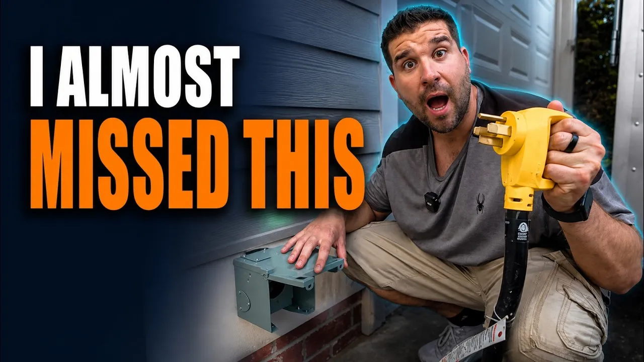
ElectricalAug 13, 202623 min video
How to install an outdoor 50 amp RV outlet
This covers running a new 50 amp, 240-volt circuit from your panel to a weatherproof NEMA 14-50 outlet on an outside wall, with the cable fished inside the walls the whole way.
- Time
- About 5½ hours, filming included
- Cost
- $344 in materials
- Pro estimates
- Up to $1,400
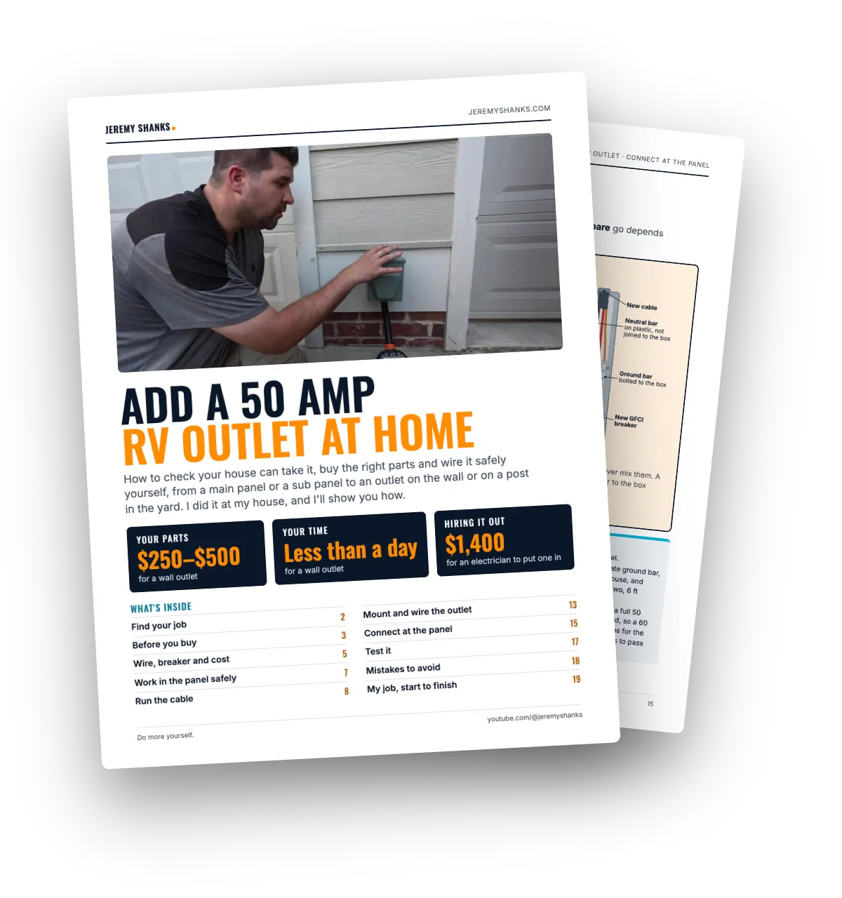
Printable guide to this video
Add a 50 Amp RV Outlet at Home
How to check your house can take it, buy the right parts and wire it safely yourself, from a main panel or a sub panel to an outlet on the wall or on a post in the yard.
- Find your job: main or sub panel, outlet on the wall or on a post in the yard
- The wire for your run, the breaker for your panel, and what it all costs
- Wiring the outlet and the panel, with drawings for main and sub panels
- Testing it before the camper goes on, and fixing what’s not right
Step by step
What you’ll need
- 6/3 with ground copper NM-B cable (consider 4 AWG on runs over about 100 feet)
- 50 amp two-pole breaker listed for your panel (GFCI type where your code requires it)
- 50 amp outdoor RV outlet box (NEMA 14-50R), listed for wet locations
- Push-in connector for a ¾-inch knockout, rated for 6/3, that installs from inside the panel
- Torque screwdriver (inch-pounds)
- Multimeter with a 600 V AC range
- 50 amp RV surge protector with indicator lights
- Fish rods and pull rope
- ¾-inch and 1-inch drill bits
- Cable cutters for 6 AWG copper
- Exterior sealant
Before you start
- Your panel needs two free spaces, and your service needs room for up to 12,000 watts more. Run the NEC 220.83 load calculation; a full panel means adding a subpanel, and an overloaded service means a bigger service first.
- Check which NEC edition your area enforces and whether you need a permit. Under the 2020 and 2023 NEC this outlet needs GFCI protection outdoors or in a garage, so you’d use a 50 amp two-pole GFCI breaker.
- Keep the cable inside the house all the way to the back of the box. NM cable isn’t allowed in wet locations, and that includes outdoor conduit, so any outside run needs a wet-rated method such as conduit with 6 AWG THWN-2 wires.
Shut off the power
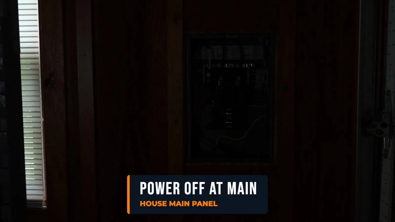
Turn off the breaker feeding the panel and confirm it’s dead with your meter. In a main panel, the incoming service wires and their lugs stay live even with the main breaker off.
Watch this step (2:22)Fish the cable into the panel
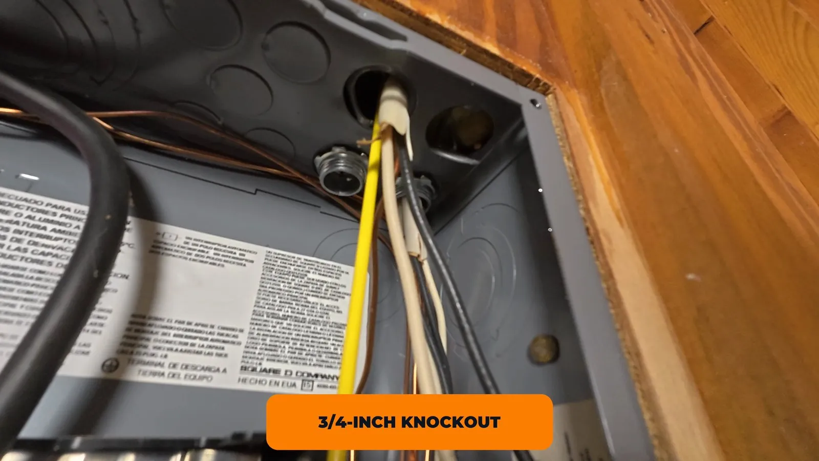
Drill a ¾-inch hole through the top plate above the panel, push fish rods down into the panel, then pull a rope back up and feed the cable down while a helper guides it. Knock out a ¾-inch knockout from the inside, slug and ring; 6/3 needs the ¾-inch size.
Watch this step (2:48)Run the cable to the outlet spot
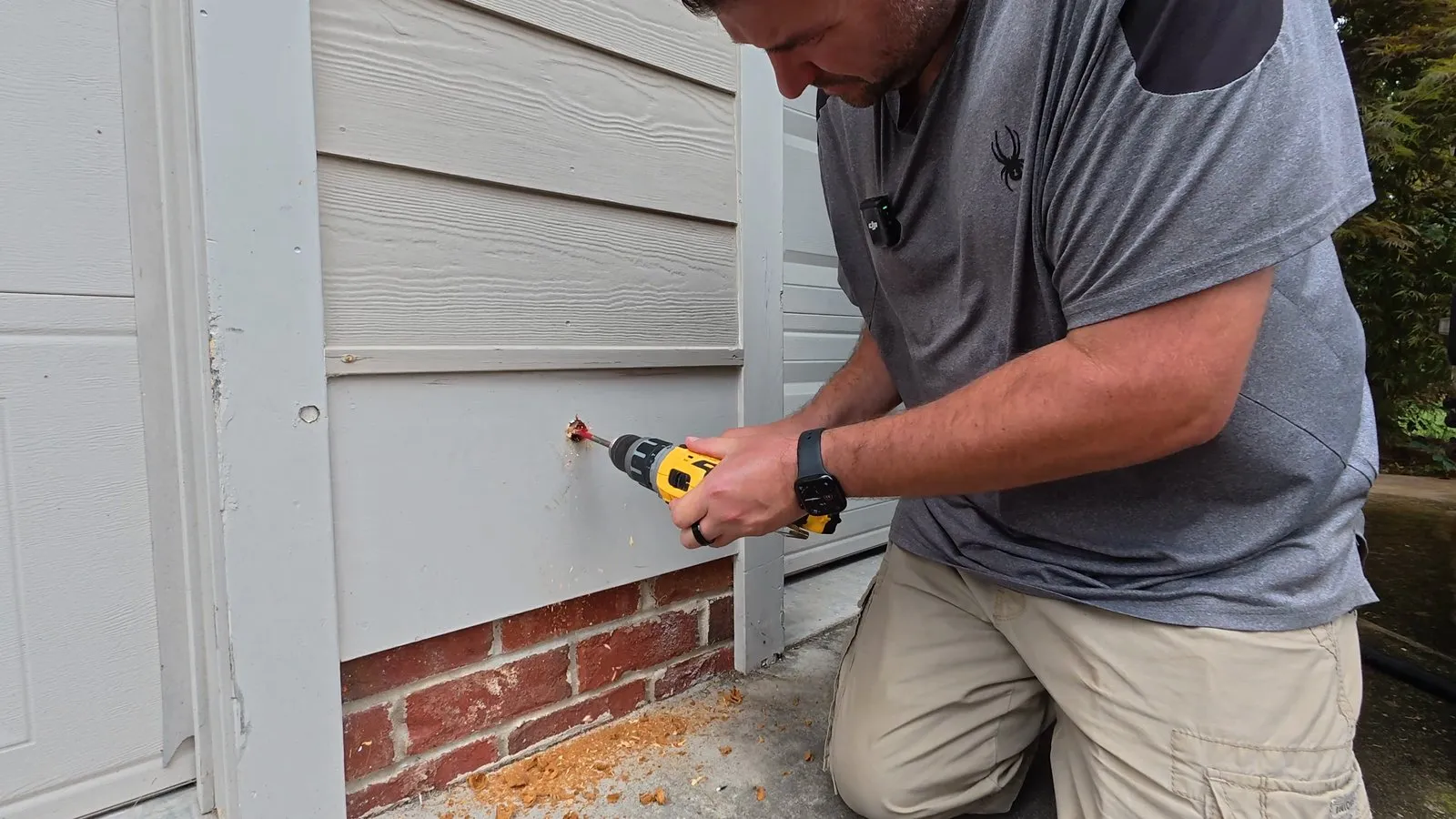
Drill a 1-inch hole through the outside wall behind the box’s rear opening, then drill the top plate above it and fish the cable down. 6/3 can’t bend tighter than five times its diameter, about 3 inches (NEC 334.24), so plan the turn into the box; I cut a small piece out of the plywood to clear a stud and get the angle.
Watch this step (7:42)Mount the outlet box
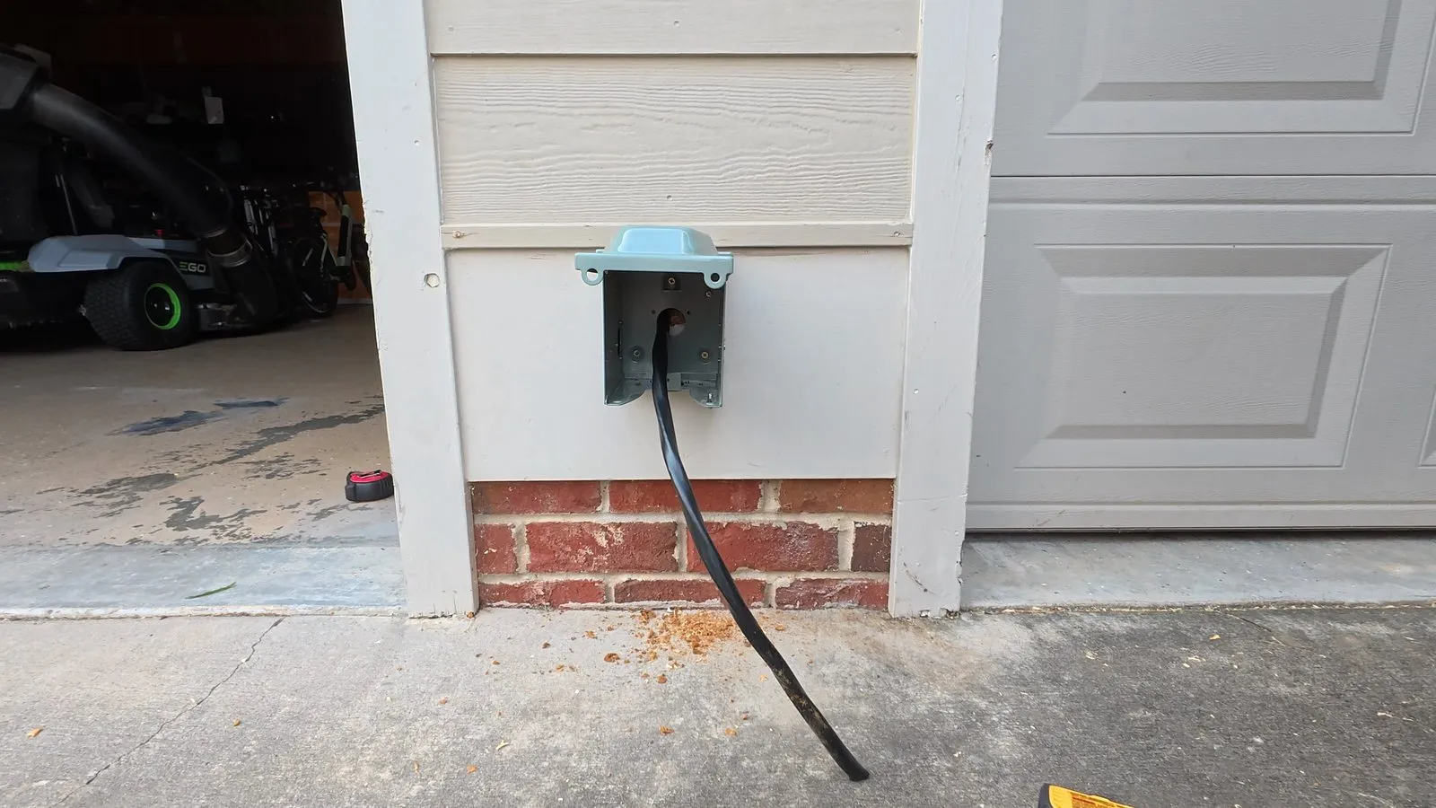
Feed the cable through a connector in the box’s rear opening before you fasten the box, leaving at least 6 inches of free wire. Level and screw the box down, then seal around the hole so water can’t get into the wall.
Watch this step (9:24)Wire the outlet
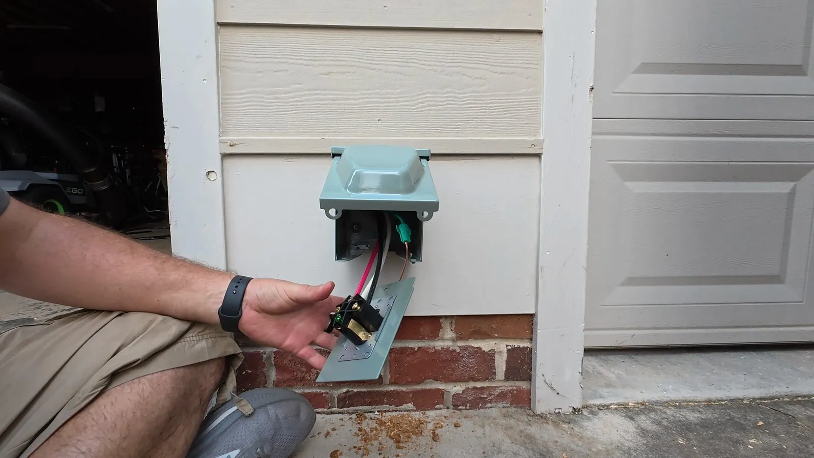
Bare ground to the box’s ground screw and the receptacle’s G (the round slot), white to W (silver), black and red to X and Y (brass). Torque each screw to the number on the receptacle, about 40 to 75 inch-pounds depending on the model.
Watch this step (10:14)Bring the cable into the panel
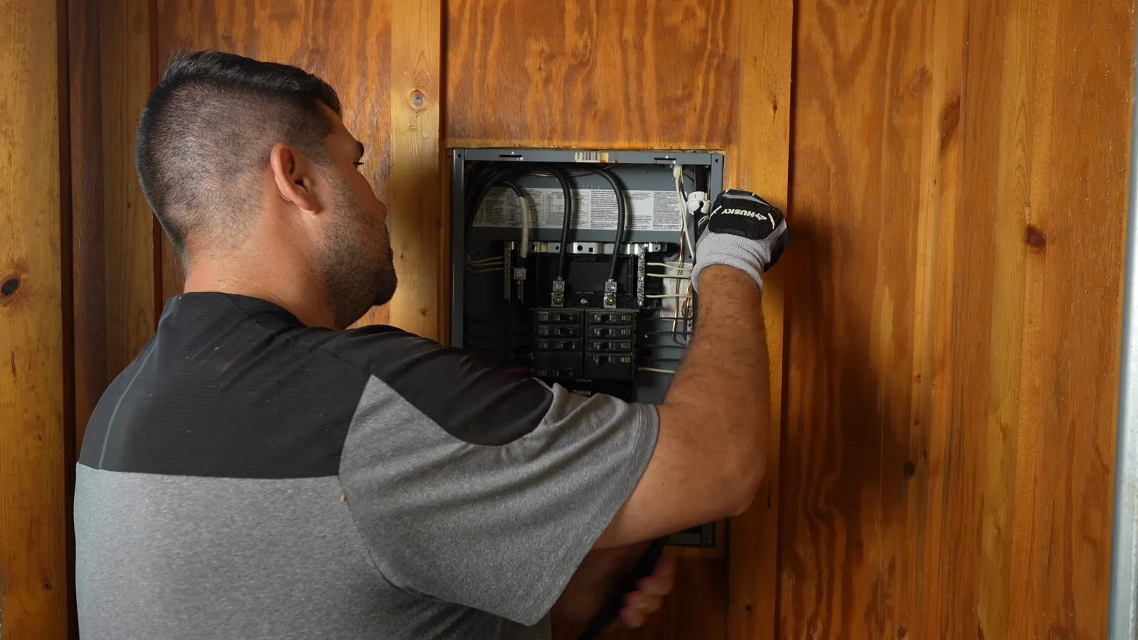
Slide the push-in connector onto the cable before you strip it, then snap it into the knockout from inside the panel so its teeth stop the cable pulling back out. Check the package says it can go in from inside; most connectors can’t.
Watch this step (13:13)Land the ground and neutral
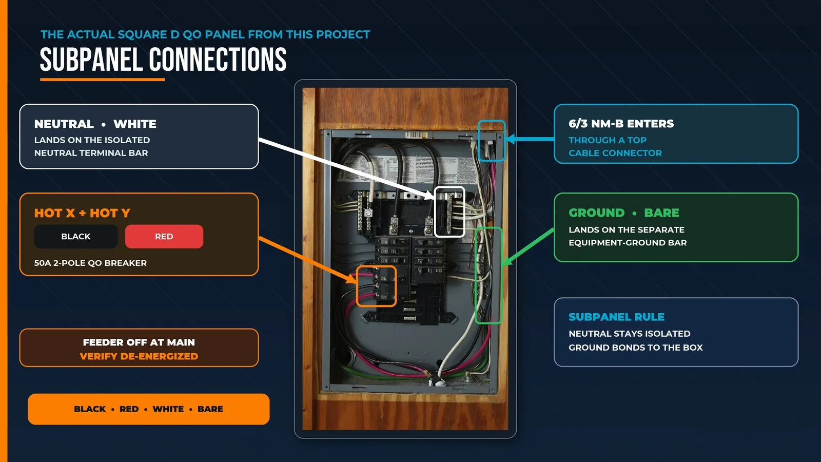
Bare ground to the ground bar, white to the neutral bar; in a subpanel those bars must stay separate (NEC 250.24(A)(5)). With a GFCI breaker, the white goes to the breaker’s neutral terminal and its coiled white pigtail to the neutral bar.
Watch this step (15:06)Install the breaker and connect the hots
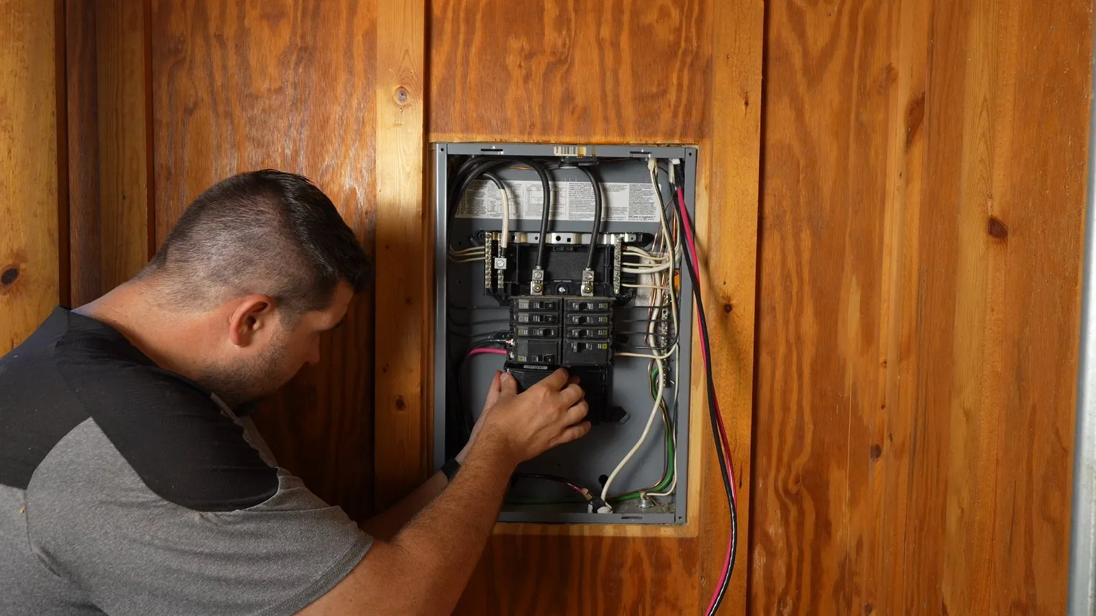
Snap the two-pole breaker onto the bus, put the black and red wires under the lug clamps (not behind them), and torque to the value on the breaker label. Write the new circuit in the panel directory.
Watch this step (16:44)Check it with an RV surge protector
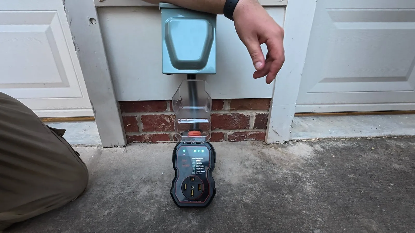
Put the panel cover on, then turn on the power and the new breaker. Plug in the RV surge protector; all green lights means the wiring checks out. Press a GFCI breaker’s test button, then reset it.
Watch this step (17:59)Confirm the voltages with a meter
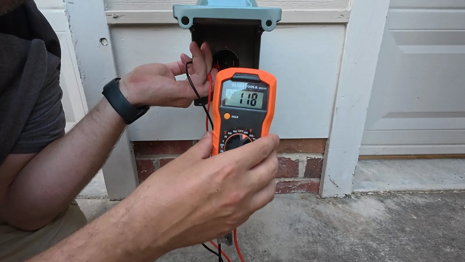
On 600 V AC you want about 240 volts across X and Y, 120 from each hot to W and to G, and near 0 from W to G (I got 118 hot to ground, 237 across). Zero across X and Y means both hots are on one leg; 240 from a hot to W means a swapped neutral. Either can wreck a camper.
Watch this step (18:31)Plug in the camper and close the lid
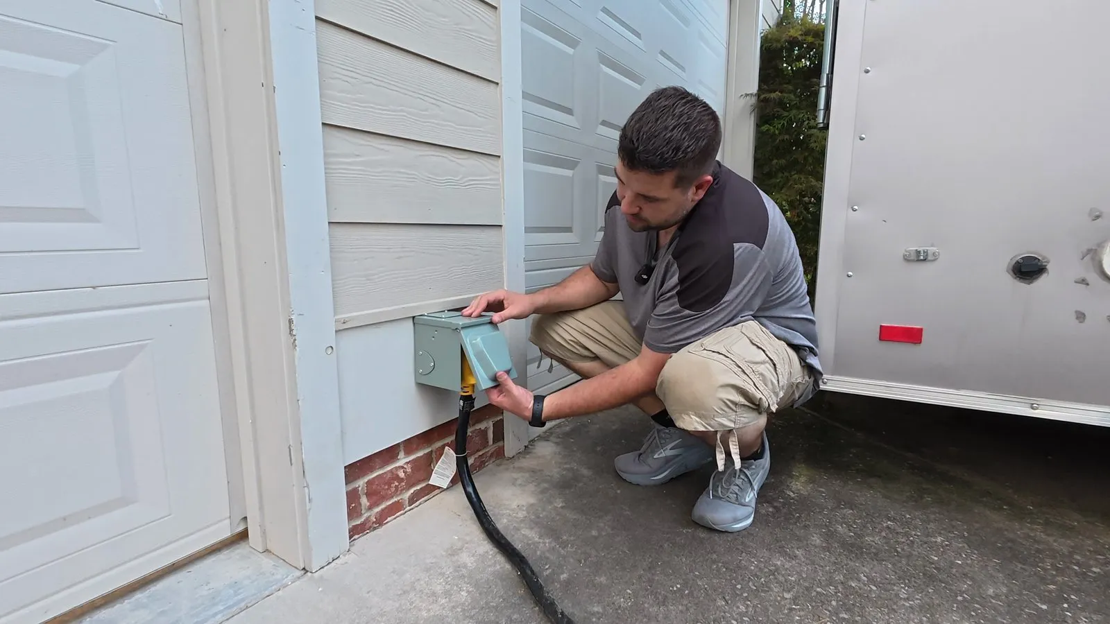
An outlet that stays plugged in outdoors has to be weatherproof with the plug in (NEC 406.9(B)(2)), so check your cord’s plug fits under the lid. My camper’s big-handled plug keeps mine from closing all the way.
Watch this step (19:36)
Mistakes to avoid
- Using 8/3 cable on a 50 amp breaker, or a 60 amp breaker on 6/3: NM is held to its 60 °C rating (40 amps for 8 AWG, 55 for 6 AWG), and a single 50 amp outlet can’t sit on a bigger breaker.
- Using 6/2 or a three-wire hookup: the camper’s 120-volt side needs a real neutral, and the bare ground can’t double as one.
- Blaming the breaker when the camper trips a GFCI: about 5 milliamps of leakage trips one, and a failing water heater element or a lot of camper electronics can add up to that.